This build started as something simple: a lucky cat which would turn on and off automatically in response to some event. Since lucky cats are associated with good fortune the idea was to make one do this every time I got paid. This was working pretty well but unfortunately, after some over-zealous poking I managed to completely knacker the internals.
What you see below is the result of asking ...what else can I do with a gold cat?
If you can't see the video above, you can see a still here.
The display uses the persistence of vision effect to generate an image 'in the air'. By repeatedly outputting light at a specific point in the rotation, and with a short enough cycle time, the viewer's eye does not register any change in brightness.
The flicker in the video is caused by the camera running at 30fps and is less apparent in person.
Managing to generate a static image depends on hitting the exact same point on the next turn around the loop. By adding a slight over- or under-scan you can make the message display rotate.
| Requirements | |||
|---|---|---|---|
| Lucky Cat Large enough to hold your other components. | amazon | ||
| Wemos D1 v2.2+ or good imitations. | amazon | ||
| L293D IC Motor driver chip. | amazon | ||
| 3-6V motor Select depending on power requirements for your construction. | amazon | ||
| 5x 100Ω resistors Ohms depends on chosen SMD. | amazon | ||
| 5x SMD LEDs Adjust resistor Ω to match. | amazon | ||
| Optional: Sockets for D1 & L293D IC If you want to be able to remove them from the board. | amazon | ||
| Slip ring 6-wire rotating connection. | amazon | ||
| Protoboard Only need a bit. | amazon | ||
| 4xAA battery pack Or whatever your motor needs. | amazon | ||
| Wires Loose ends, or jumper leads. | |||
| Bit of wood 40mm x 40mm x 45mm. | |||
| Zip ties To hold the motor on. | |||
| Glue Lots of glue. | |||
| Dremel or other rotary tool To make holes for the axle & wires. | amazon | ||
The build is described below in parts, including the construction of the motor mechanism, the LED display and the driver board. If you just want the code, jump to the end. There should be enough detail here to hack together your very own lucky message cat!
The cat
Lucky cats are available to buy quite cheaply and come in various versions and colours. The model I ended up with seems quite common and is recommended, since it has a lot of working room inside.

The shell is made entirely of moulded plastic, with a gold sheen. The plastic is flexible, apart from where the shape gives it structural strength. However, the gold colour is very susceptible to solvents in glues. My cat ended up quite patchy by the time I was finished with it.
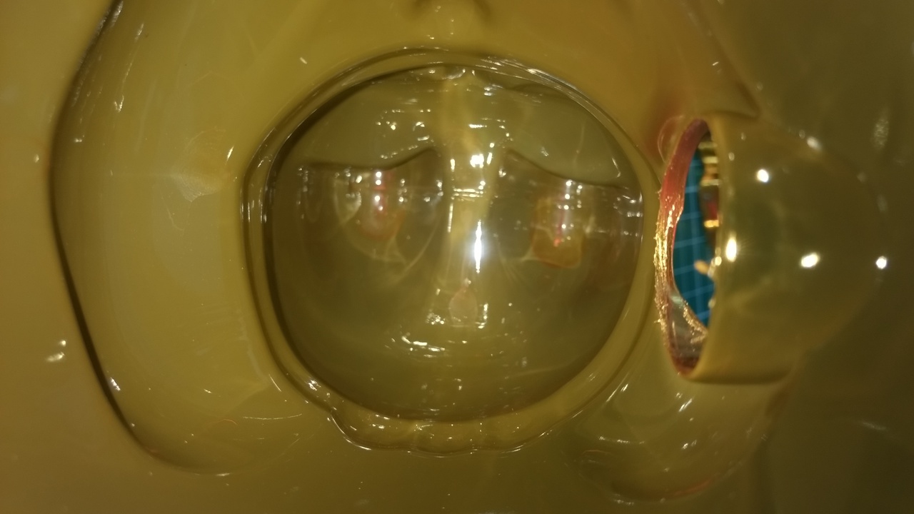
POOP: Despite appearances this is not a picture of the inside of my colon.
Motor support
The original mechanism inside a lucky cat uses an electromagnetic coil coupled with a small controller circuit powered by a single 1.5V battery. The arm is attached to a horizontal beam off which a magnet is suspended on a pendulum. The arm rocking mechanism rests inside on top of 4 legs, which we will use to hold our axel mount (a block of wood). The existing mechanism can be unscrewed from the top by removing the 4 tiny screws via the holes in the base.
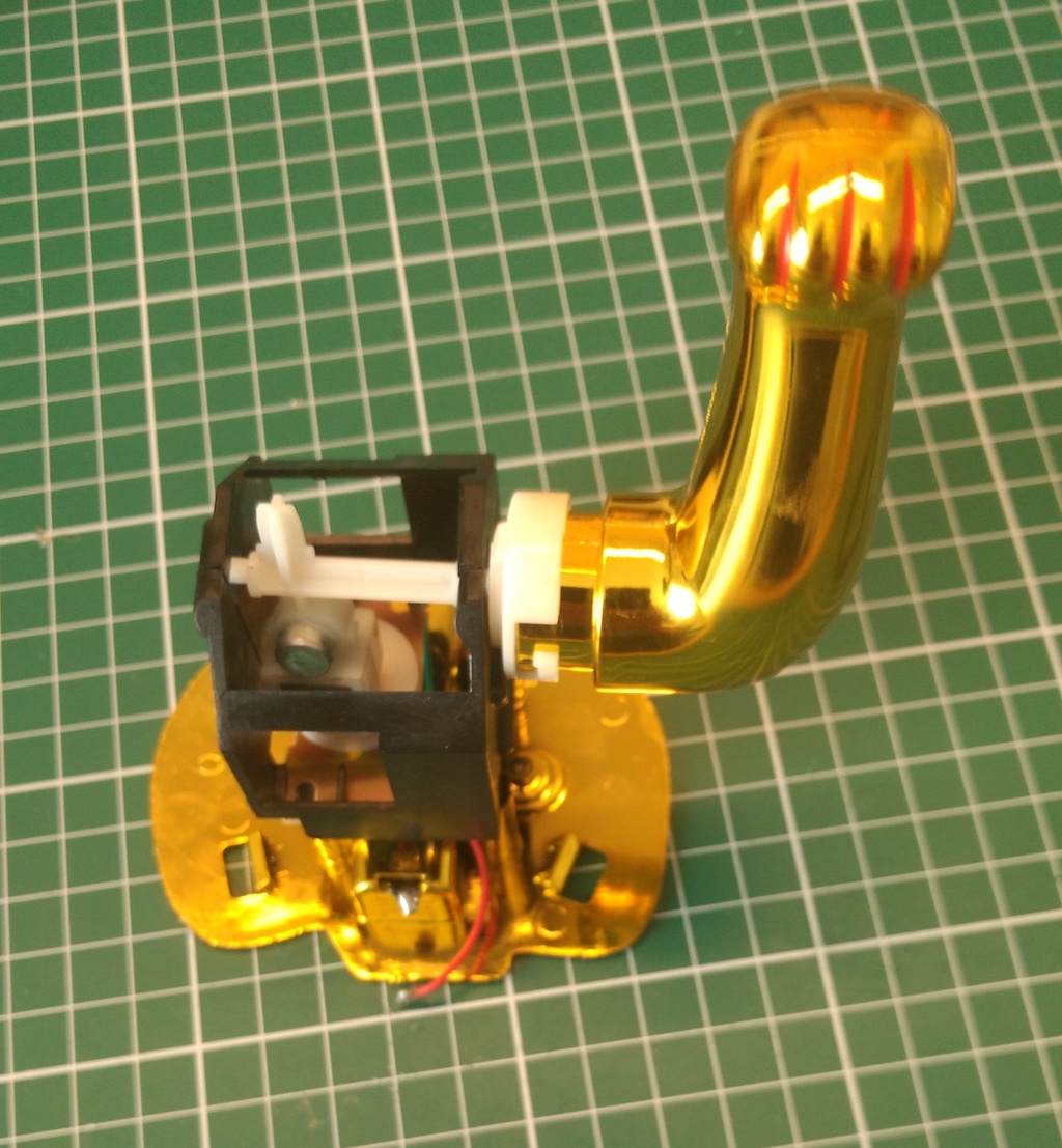
There wasn't a simple way to make use of the mount to hold a motor, so I replaced it outright with a block of wood 40mm x 40mm x 45mm.
To position the axle the block was screwed onto the top of the mechanism legs, using the same screws, and then reassembled the cat. The axle was positioned to be in the middle of the arm hole, marked with a pencil and then drilled through on a drill press.
When drilling the axle hole pick a size which is as close-as but slightly wider than the diameter of your axle. Too wide will give wobble, too narrow and it'll get stuck.
Motor mechanism
The gears, axle and arm-mount connector I used for this build were all taken from the remains of the tank chassis used in the KropBot Mk I. This is a pretty inefficient way to get parts, and you can find better axle and gear parts bundles online. The axle needs to be about 65-75mm long.
The 3-6V motor sits on top of the mounting block and is then fastened into place with loops of zip ties. A couple of loops was enough to hold it in place, but still allow for manual adjustment.
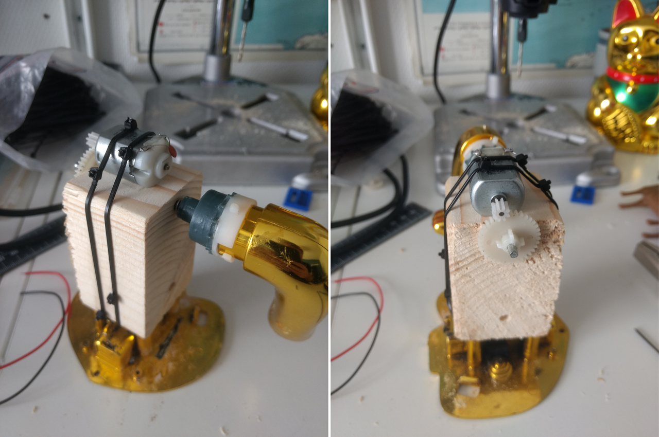
Because of the gears available the motor could sit directly above the axle gear. A small offset backwards gave it enough space for the gears to mesh, but then the motor gear bumped the inside of the shell. I had to trim the motor axle down with a rotary tool to get it to fit.
Depending on whether you offset the motor forward or backward, it might run easier forwards or backwards. Bear that in mind later.
To allow power for the LEDs to be transferred across the rotating joint, I used a slip ring. The ones I bought were pretty chunky and to be able to get them inside the cat they needed to be recessed into the support block. The simplest way to do this was cut a chunk out of it. The slip ring was then screwed onto the block for support. After reassembling the cat a few times it was lined up enough to work.
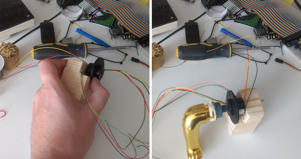
While adjusting the block I screwed up my measurement and lopped off a bit too much. I then made things worse by using balsa to build it back up — balsa is too weak for the screws to hold it. Copious amounts of glue was the only answer.
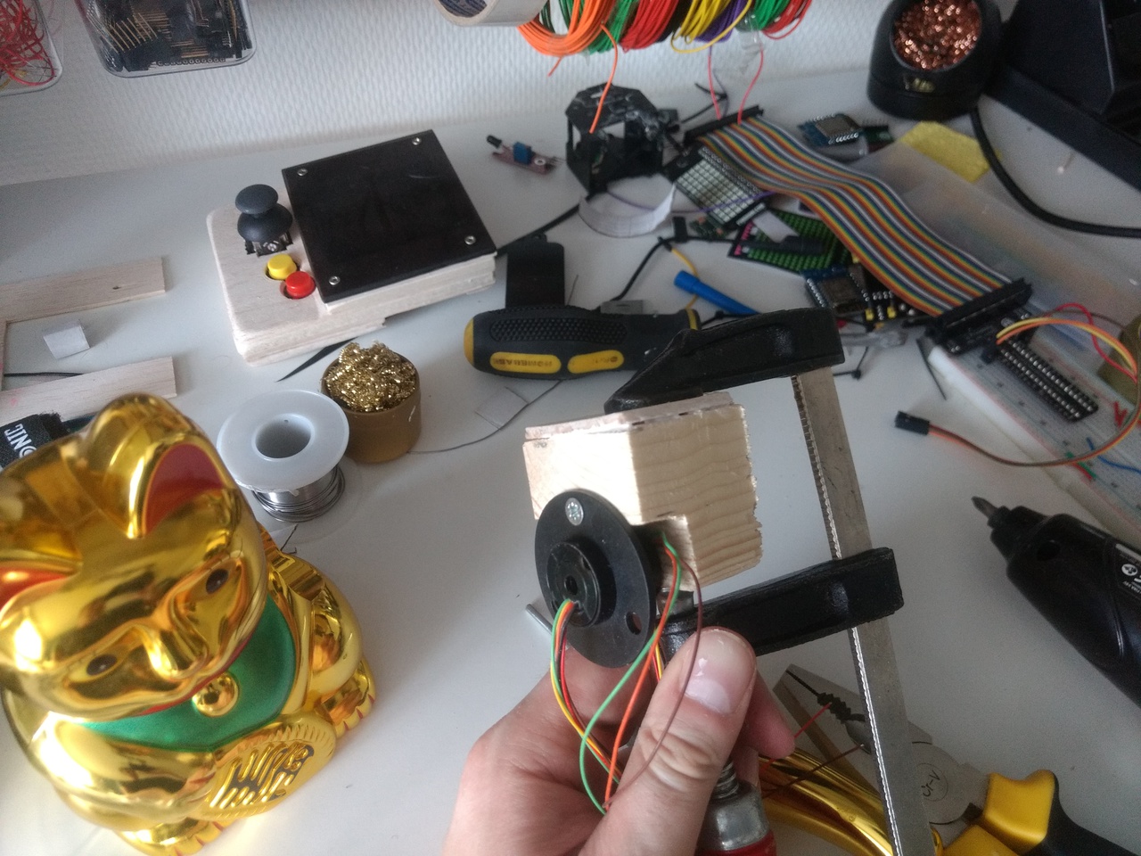
Use more glue.
Once I was convinced everything lined up, the gear mechanism was disassembled and everything covered in silicone grease. Then it was reassembled, zip-tied and had the crap glued out of it.
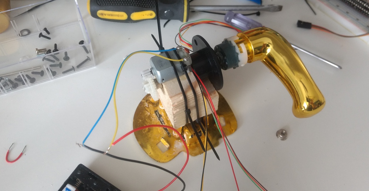
To fix (some of) the wobble rotating at full speed I packed some folded paper into the space between the axle and the rotating inner ring of the slip ring. With this in place the rotation of the arm pulls the slip-ring with it, and the arm doesn't pull the axle up and down so much. It's not great, but it helps things a little.
Circuit
The complete schematic for the motor & LED driver circuit for our message cat is shown below.
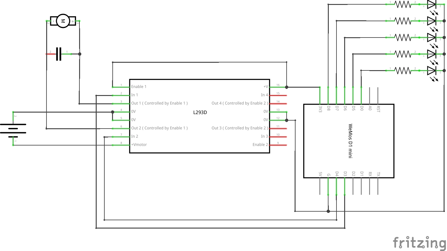
The motor driver circuit is based on an L293D. The L293D is a 16 pin DIP containing two independent H-bridges circuits for dual-motor dual-direction control. Here we're only using a single motor, and usually only drive it in a single direction, so it's a bit of overkill — but it's what I had in my box. The inputs and outputs for each motor are on either side of the package, and there are 2 input pins, 2 output pins and 1 enable pin for each motor.
| Pin | Function | Notes |
|---|---|---|
| 1 | Enable 1 & 2 | HIGH to enable motor outputs 1 & 2 (left side) |
| 2 | Input 1 | HIGH to drive current through output 1 |
| 3 | Output 1 | Connect to terminal 1 of Motor A |
| 4,5 | GND | Common ground for motor & IC, act as heatsink |
| 6 | Output 2 | Connect to terminal 2 of Motor A |
| 7 | Input 2 | HIGH to drive current through output 2 |
| 8 | VCC Motor | Motor supply, from batteries |
| 16 | VCC IC (+5V) | IC supply, from microcontroller |
| 15 | Input 4 | HIGH to drive current through output 4 |
| 14 | Output 4 | Connect to terminal 2 of Motor B |
| 13,12 | GND | Common ground for motor & IC, act as heatsink |
| 11 | Output 3 | Connect to terminal 1 of Motor B |
| 10 | Input 3 | HIGH to drive current through output 3 |
| 9 | Enable 3 & 4 | HIGH to enable motor outputs 3 & 4 (right side) |
The IC can handle heavy currents and may generate a lot of heat. The 4 grounding pins are provided as a simple way to shed some of this heat, by acting as a basic heatsink. Make sure to solder them all to the board.
Since DC motors are inductive loads, and can generate back current when drive power is stopped or reversed. This voltage fluctuation could potentially damage the IC so a small ceramic capacitor is used to dampen this.
LEDs
The display uses 5 LEDs to give a reasonable, minimal horizontal resolution for text display. This was helpfully also about the right width using SMD LEDs and matched the number of wires available on the slip ring (6; 5 +ve, 1 GND). The vertical size of characters is entirely independent, as it is generated as the arm rotates.
It might be possible to fit more SMDs horizontally if you're good at soldering, but you'll need to get a different slip ring and get a different font.
Wiring
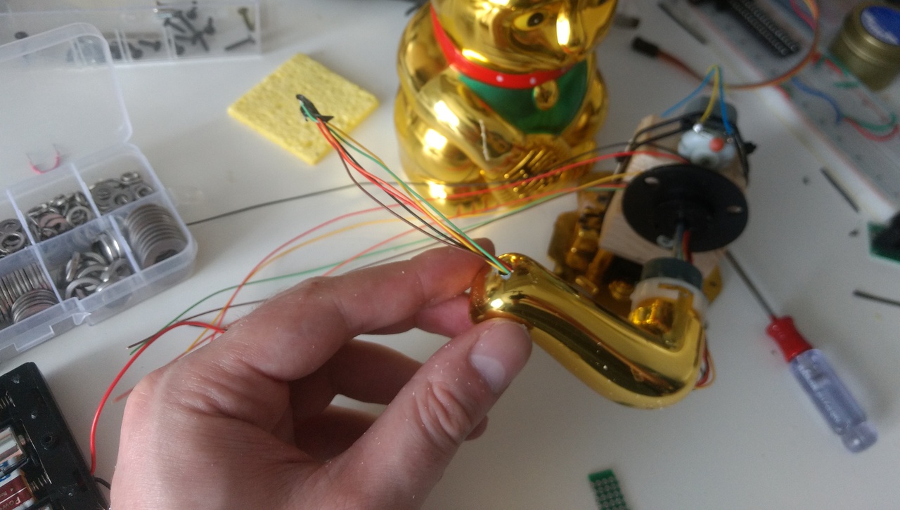
In the initial build the arm was connected by a screw adapter, taken from the cat's original arm mount. With this setup the wires had to enter the arm from the 'outside', and a small hole was drilled in the base of the arm for the wires to feed in. This was replaced after the attachment failed (see later).
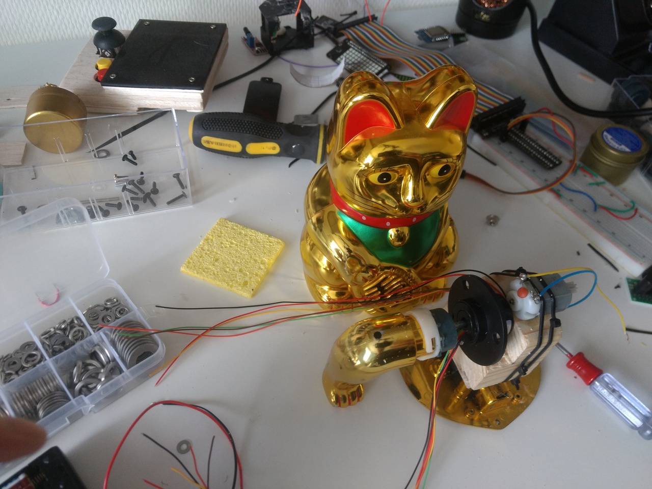
I drilled a second hole at the knuckle, and the 6 wires were taped together and pushed up and out.
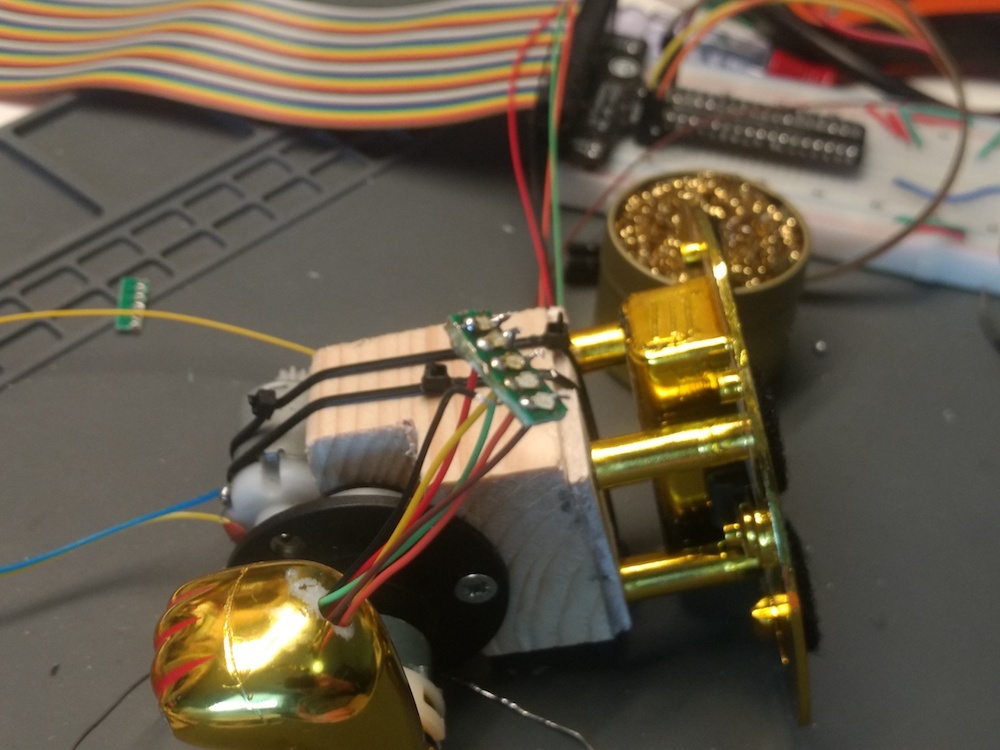
Board
Five red SMD LEDs were soldered on a small chunk of protoboard. I used red for the appearance, but white LEDs would be considerably brighter. The power wires were soldered from behind, and then the LEDs soldered on top. This wasn't ideal, and they ended up not exactly parallel, but it meant the wires could be kept out of view.
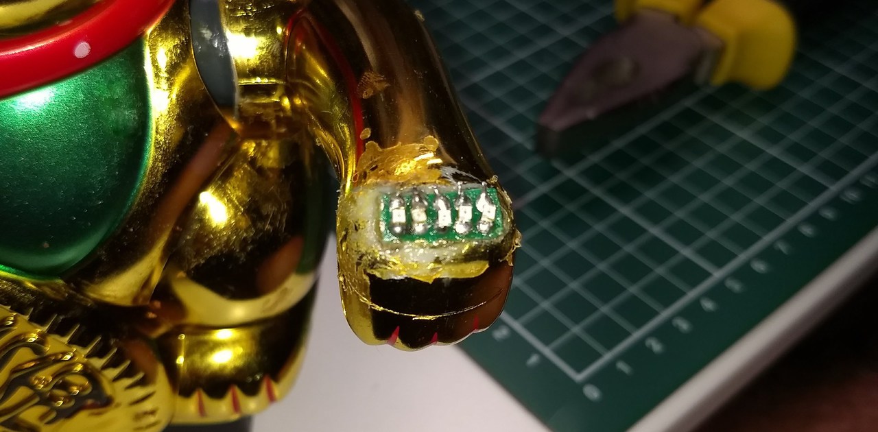
There were a few different ways to mount the LED display board on the hand, but I opted to cut a larger hole and recess them into it. Cutting the hole to fit as closely as possible and then relying on glue to make it stay in place. It's a bit of a mess up close, but not noticeable from a distance or when rotating.
Control
Because there are only 5 LEDs the control can be handled directly by GPIO pins. This
keeps the control circuit for those very simple, with just resistors in series.
The photo below shows the LEDs wired up to GPIO pins on the Wemos D1 with all pins HIGH.
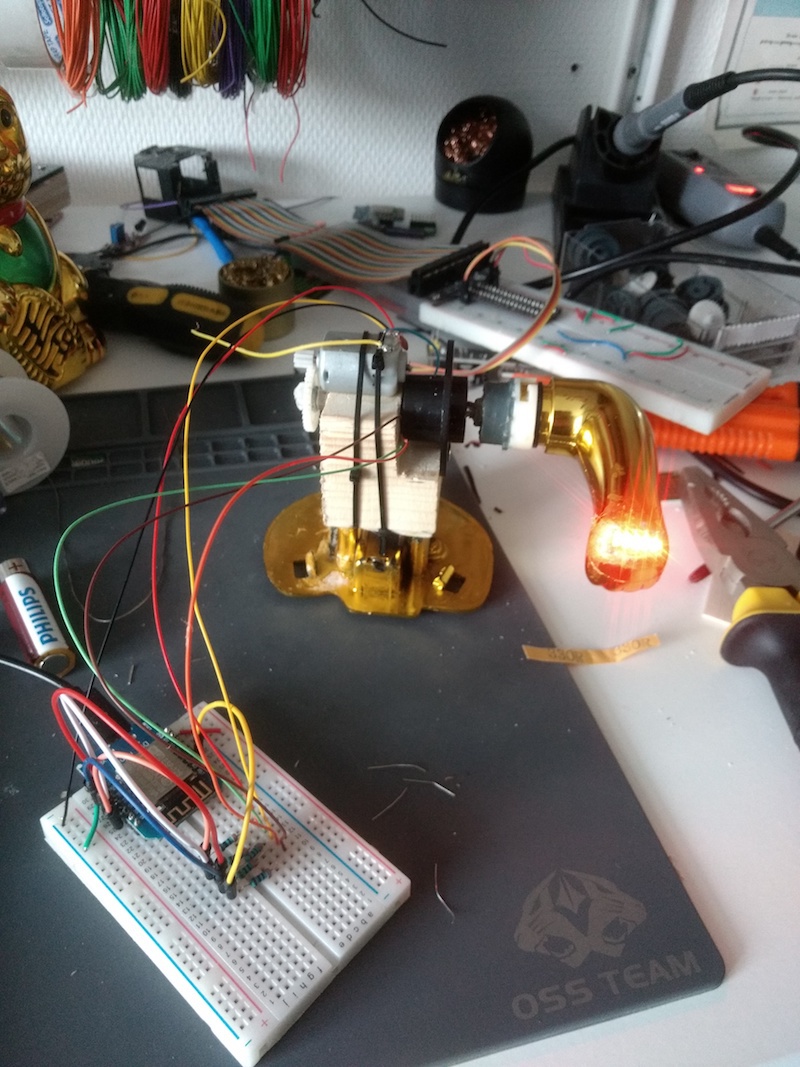
For a quick test run, I wired the Wemos D1 and LEDs up using a breadboard and wrote a quick script to iterate over an array of values spelling out POOP — a palindrome, so it doesn't matter which way the arm spins.
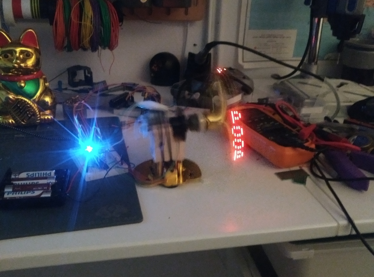
Fiddling with the speed showed there was a good bit of leeway for generating messages of different lengths, and I could tune the output so the LEDs landed on the same point (or thereabouts) on each rotation. You can see from the blur on the mounting block that this was shaking quite a bit at the time — the final version runs the arm quite a bit slower so it doesn't try and get airborne.
Driver board
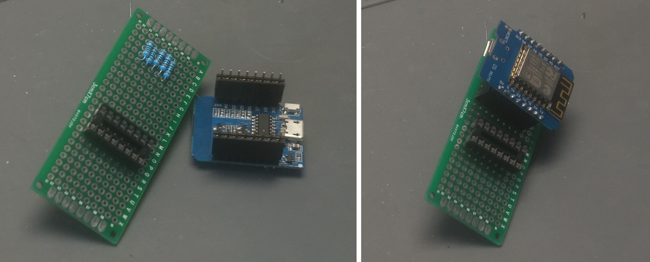
The goal for the driver board itself was to be able to slot the board in under the main gear, with enough clearance for it to rotate cleanly. The board was wired up on a small chunk of protoboard — wide enough to fit the D1 across the board, with space below for the L293D. Resistors were mounted under the D1 to save vertical space.
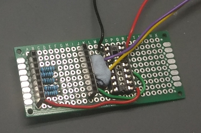
The completed & cropped control board, with motor drive wires (thick purple, thick yellow), LED driver wires (thin 5 colours) and motor power in (thick red, thick black). The underside is a bit messier than it should be as I stupidly tried to rework the L293D wiring in the process of moving from the breadboard. Thankfully I didn't release any magic smoke.
Don't be me. If you need to change something, re-prototype on the breadboard first.
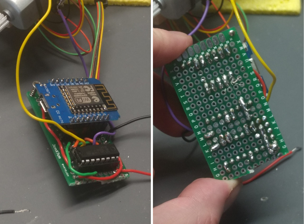
With the wiring in place, I did a quick test everything with the control board to ensure everything was working as expected. After fixing a few dodgy solder joints, all the LEDs lit and the motor could turn both ways.
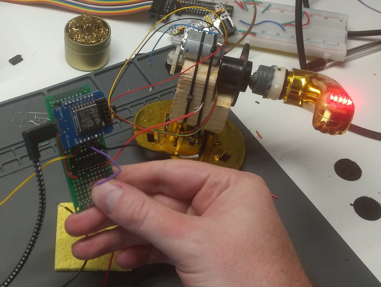
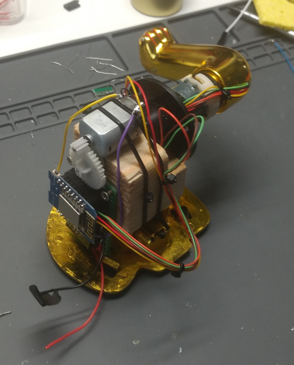
The control board mounted with screws onto the side of the motor mount. It landed just short of where the drive cog, leaving it free to rotate without needed any adjustment.
To support developers in [[ countryRegion ]] I give a [[ localizedDiscount[couponCode] ]]% discount on all books and courses.
[[ activeDiscount.description ]] I'm giving a [[ activeDiscount.discount ]]% discount on all books and courses.
Assembly & final bodges
Unfortunately the combined height of the D1 on top of the control board and motor mount was too large to fit through hole in the bottom of the cat shell.
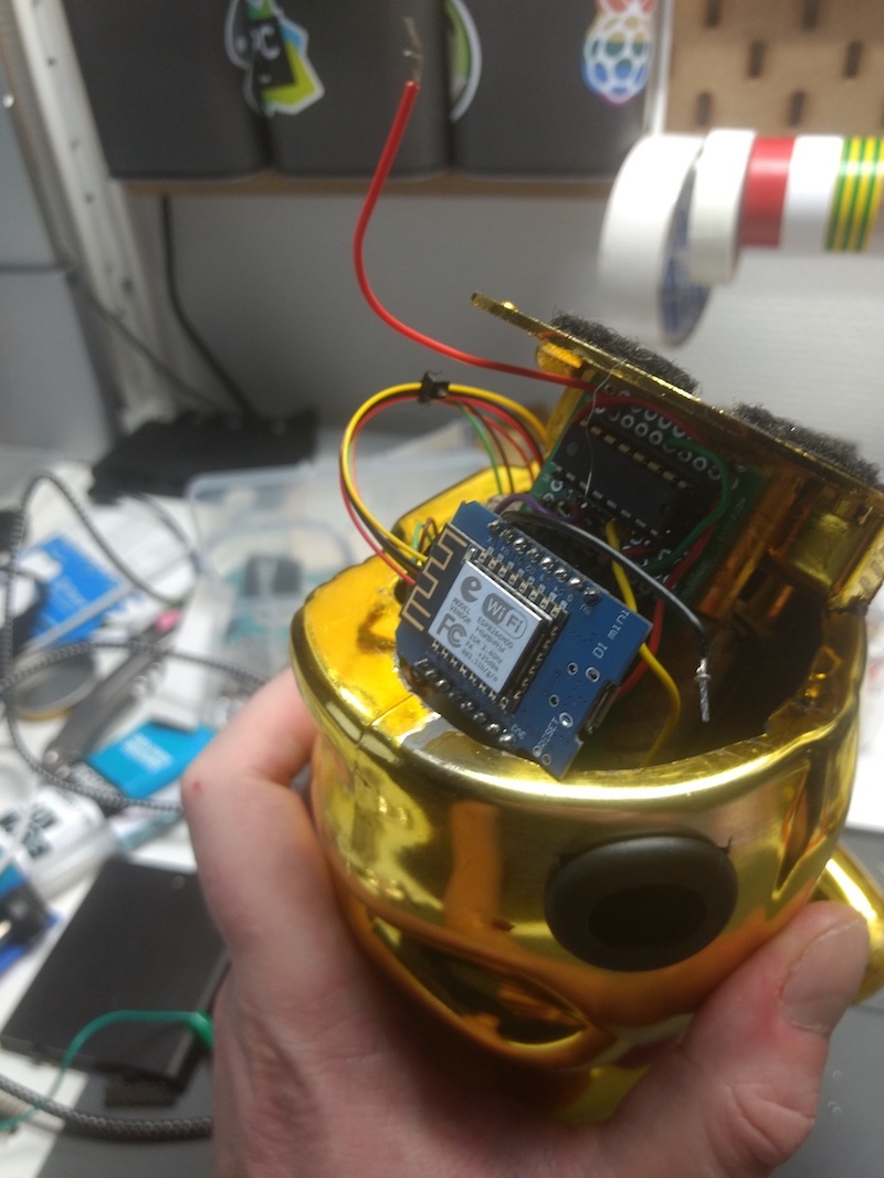
The shell was pared back with a craft knife until it fit. The motor mount rotated up and around until it poked out the arm hole. I also had to trim the motor drive shaft with a dremel as it was pressing against the inside.
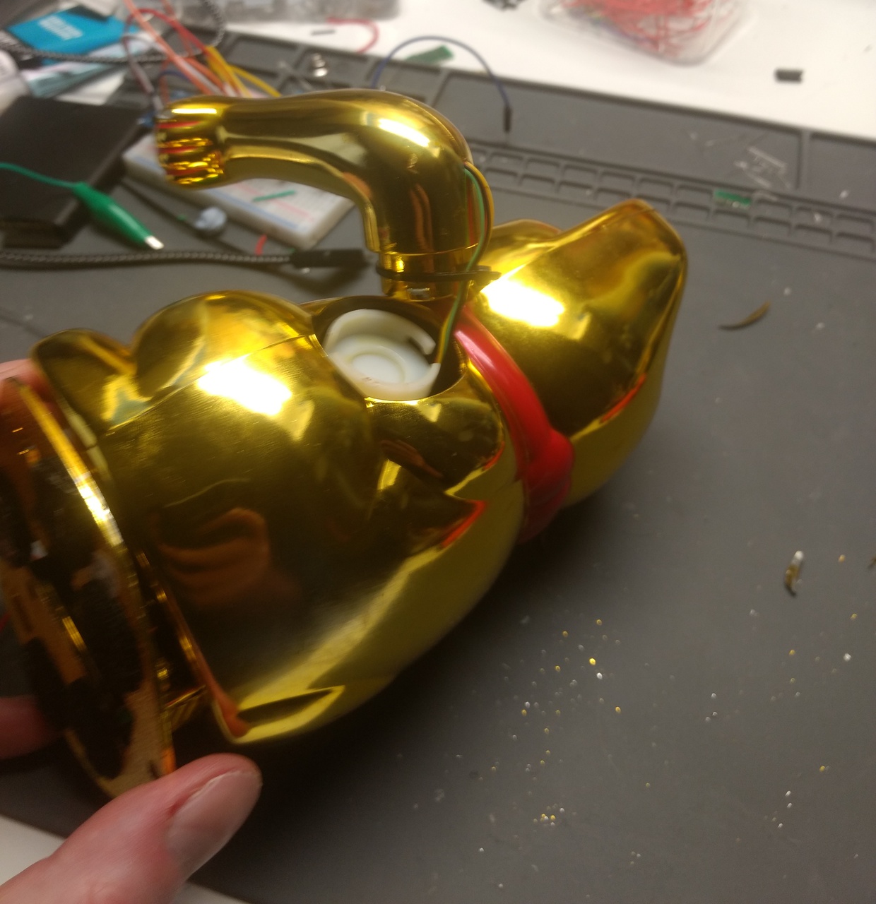
The hole in the back of the cat — from previous misadventures — was taped up to get rid of sharp edges. This is where the USB power lead enters to power the D1, the motor wires (seen in the photo below) actually exit via the base to the AA battery pack.
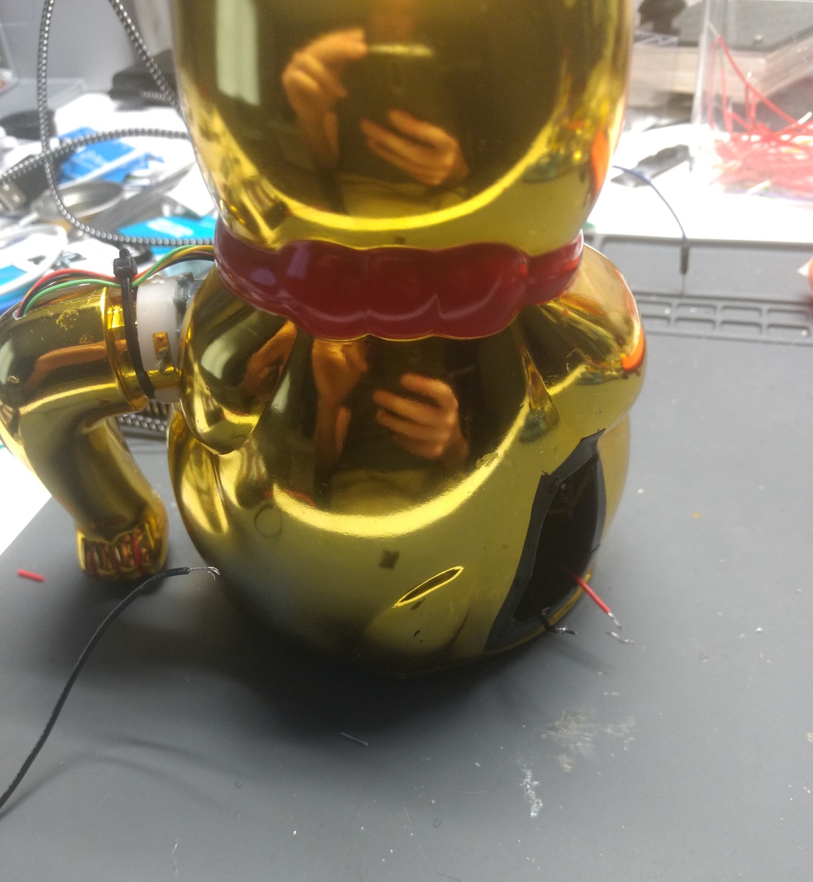
The photo below shows the wires for the LEDs in the original arrangement where they enter the base of the arm. They knocked against the shell while rotating making an annoying knocking sound. I was looking for ways to fix this, when the mount-lock on the end of the arm cracked open presenting a solution: more glue. The mount was cut off, the wires moved to the inside and the arm pushed over the mount, then glued in place.
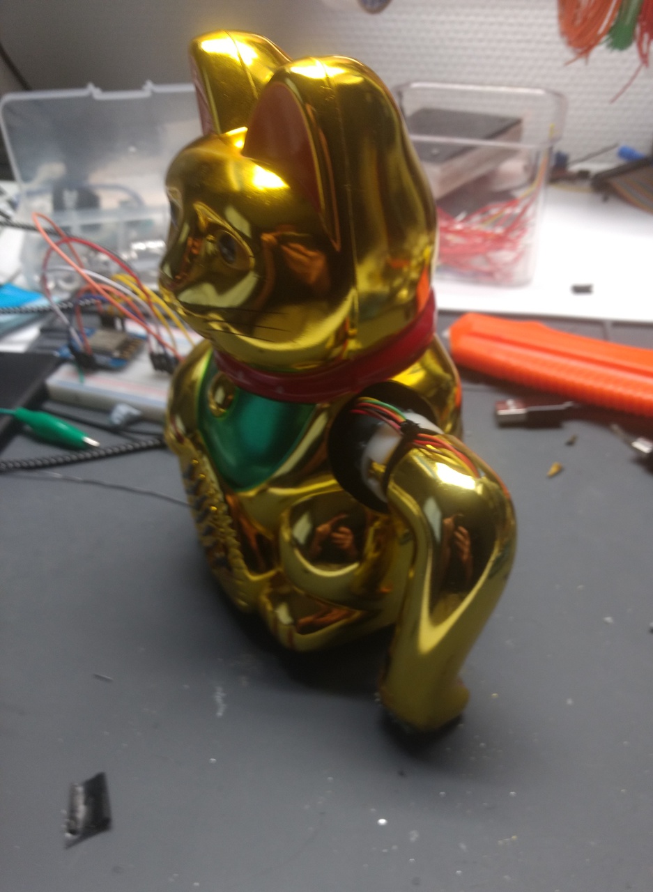
The final step was to mount the cat on top of a battery pack — for stability/weight as well as power. The bottom of the battery case was also affixed to the table with velcro pads, to minimise the shaking while taking photo & video of it running.
Code
The display code needs to do a few things —
- Get the arm spinning at a fast enough speed but not so fast we can't get text out in time. The speed should be constant(-ish).
- Turn the LEDs on and off, as close to row-by-row as possible, to generate characters as the arm rotates. Using a font with max 5-pixel width.
- Time both the above so that each time the arm rotates the display of text happens in roughly the same place as the last rotation.
With all of those in place, we should have a functional persistance-of-vision LED display for short messages. Below is breakdown of the code I used to achieve this on my lucky cat.
Character Set
For the text we're using a simple 5x7 pixel display font, based on Adafruit's
glcdfont.c.
This has been converted to Python list of tuple structure. The character set is
in ASCII order, including the first 128 symbols. A few custom symbols were added on
top, including —
| Code | Symbol | Bytes |
|---|---|---|
| 128 | Heart | 0x0c, 0x1e, 0x3c, 0x1e, 0x0c |
| 129 | Python | 0x18, 0x3a, 0x3e, 0x2e, 0x0c |
| 130 | Aubergine | 0x1c, 0x3e, 0x7f, 0x73, 0x66 |
| 131 | Poop | 0x40, 0x71, 0x78, 0x62, 0x40 |
| 132 | Cat | 0x3c, 0x57, 0x4c, 0x57, 0x3c |
You can generate your own custom characters using this tool. Make sure to select column major and little endian. There is no width 5 option, or height 7 option. Use 6 & 8 and keep to the top left. After generating copy the first 5 values only.
Each character is represented by a tuple of 5 int values (with byte range 0-255)
covering the 5 pixel width. The binary representation of each of these
values determines whether a given pixel is on/off vertically down the character.
This wastes a lot of memory, but keeps the later code simple.
CHARSET = [
    (0, 0, 0, 0, 0),
    (62, 91, 79, 91, 62),
    (62, 107, 79, 107, 62),
    (28, 62, 124, 62, 28),
    (24, 60, 126, 60, 24),
    (28, 87, 125, 87, 28),
    (28, 94, 127, 94, 28),
    (0, 24, 60, 24, 0),
    (255, 231, 195, 231, 255),
    (0, 24, 36, 24, 0),
    (255, 231, 219, 231, 255),
    (48, 72, 58, 6, 14),
    (38, 41, 121, 41, 38),
    (64, 127, 5, 5, 7),
    (64, 127, 5, 37, 63),
    (90, 60, 231, 60, 90),
    (127, 62, 28, 28, 8),
    (8, 28, 28, 62, 127),
    (20, 34, 127, 34, 20),
    (95, 95, 0, 95, 95),
    (6, 9, 127, 1, 127),
    (0, 102, 137, 149, 106),
    (96, 96, 96, 96, 96),
    (148, 162, 255, 162, 148),
    (8, 4, 126, 4, 8),
    (16, 32, 126, 32, 16),
    (8, 8, 42, 28, 8),
    (8, 28, 42, 8, 8),
    (30, 16, 16, 16, 16),
    (12, 30, 12, 30, 12),
    (48, 56, 62, 56, 48),
    (6, 14, 62, 14, 6),
    (0, 0, 0, 0, 0),        # 32: space
    (0, 0, 95, 0, 0),
    (0, 7, 0, 7, 0),
    (20, 127, 20, 127, 20),
    (36, 42, 127, 42, 18),
    (35, 19, 8, 100, 98),
    (54, 73, 86, 32, 80),
    (0, 8, 7, 3, 0),
    (0, 28, 34, 65, 0),
    (0, 65, 34, 28, 0),
    (42, 28, 127, 28, 42),
    (8, 8, 62, 8, 8),
    (0, 128, 112, 48, 0),
    (8, 8, 8, 8, 8),
    (0, 0, 96, 96, 0),
    (32, 16, 8, 4, 2),
    (62, 81, 73, 69, 62),   # 48: 0
    (0, 66, 127, 64, 0),
    (114, 73, 73, 73, 70),
    (33, 65, 73, 77, 51),
    (24, 20, 18, 127, 16),
    (39, 69, 69, 69, 57),
    (60, 74, 73, 73, 49),
    (65, 33, 17, 9, 7),
    (54, 73, 73, 73, 54),
    (70, 73, 73, 41, 30),
    (0, 0, 20, 0, 0),
    (0, 64, 52, 0, 0),
    (0, 8, 20, 34, 65),
    (20, 20, 20, 20, 20),
    (0, 65, 34, 20, 8),
    (2, 1, 89, 9, 6),
    (62, 65, 93, 89, 78),
    (124, 18, 17, 18, 124), # 65: A
    (127, 73, 73, 73, 54),
    (62, 65, 65, 65, 34),
    (127, 65, 65, 65, 62),
    (127, 73, 73, 73, 65),
    (127, 9, 9, 9, 1),
    (62, 65, 65, 81, 115),
    (127, 8, 8, 8, 127),
    (0, 65, 127, 65, 0),
    (32, 64, 65, 63, 1),
    (127, 8, 20, 34, 65),
    (127, 64, 64, 64, 64),
    (127, 2, 28, 2, 127),
    (127, 4, 8, 16, 127),
    (62, 65, 65, 65, 62),
    (127, 9, 9, 9, 6),
    (62, 65, 81, 33, 94),
    (127, 9, 25, 41, 70),
    (38, 73, 73, 73, 50),
    (3, 1, 127, 1, 3),
    (63, 64, 64, 64, 63),
    (31, 32, 64, 32, 31),
    (63, 64, 56, 64, 63),
    (99, 20, 8, 20, 99),
    (3, 4, 120, 4, 3),
    (97, 89, 73, 77, 67),
    (0, 127, 65, 65, 65),
    (2, 4, 8, 16, 32),
    (0, 65, 65, 65, 127),
    (4, 2, 1, 2, 4),
    (64, 64, 64, 64, 64),
    (0, 3, 7, 8, 0),
    (32, 84, 84, 120, 64),  # 97: a
    (127, 40, 68, 68, 56),
    (56, 68, 68, 68, 40),
    (56, 68, 68, 40, 127),
    (56, 84, 84, 84, 24),
    (0, 8, 126, 9, 2),
    (24, 164, 164, 156, 120),
    (127, 8, 4, 4, 120),
    (0, 68, 125, 64, 0),
    (32, 64, 64, 61, 0),
    (127, 16, 40, 68, 0),
    (0, 65, 127, 64, 0),
    (124, 4, 120, 4, 120),
    (124, 8, 4, 4, 120),
    (56, 68, 68, 68, 56),
    (252, 24, 36, 36, 24),
    (24, 36, 36, 24, 252),
    (124, 8, 4, 4, 8),
    (72, 84, 84, 84, 36),
    (4, 4, 63, 68, 36),
    (60, 64, 64, 32, 124),
    (28, 32, 64, 32, 28),
    (60, 64, 48, 64, 60),
    (68, 40, 16, 40, 68),
    (76, 144, 144, 144, 124),
    (68, 100, 84, 76, 68),
    (0, 8, 54, 65, 0),
    (0, 0, 119, 0, 0),
    (0, 65, 54, 8, 0),
    (2, 1, 2, 4, 2),
    (60, 38, 35, 38, 60),

    # Custom symbols.
    (0x0c, 0x1e, 0x3c, 0x1e, 0x0c), # Heart
    (0x18, 0x3a, 0x3e, 0x2e, 0x0c), # Python
    (0x1c, 0x3e, 0x7f, 0x73, 0x66), # Aubergine
    (0x40, 0x71, 0x78, 0x62, 0x40), # Poop
    (0x3c, 0x57, 0x4c, 0x57, 0x3c), # Cat
]
Using the above character table, outputting each character as we rotate the arm
would require us to convert each column to binary, select the current vertical
position from this, and toggle LED based on the value (0 or 1). Rotating at
full-whack this is quite a lot to accomplish. If it takes a long time to calculate each
row the characters become very large (as the arm rotates while it is happening).
If the inter-pixel delay is too large, the characters become distorted.
To move as much delay out of the display loop as possible, we can pre-process the character data for a given message and convert it into a straight pixel-array. This eliminates the conversion and lookup from the display loop, turning into a simple iteration.
We could speed this up even more using an external shift register. Each row would be drawn by sending a single byte to the register to update all LEDs in a single operation.
def build_message_display(message, length):
    result = []
    for char in reversed(message):
        glyph = CHARSET[ord(char)]
        build = []
        for line in glyph:
            build.append([1 if c == '1' else 0 for c in "{0:07b}".format(line)])

        for y in range(7):
            result.append([build[x][y] for x in range(5)])

        # Blank line between letters
        result.append([0,0,0,0,0])
        result.append([0,0,0,0,0])

    # Pad to the vertical resolution of the display.
    text_len = len(result)
    if text_len < length:
        for _ in range(length-text_len):
            result.append([0,0,0,0,0])

    return result
Setup
For the display we create 5 output pins, one for each LED, and arranged in a list LEDS
so we can iterate over them easily in the display code. We also need to setup the
output pin to control the LS motor driver. We only actually use Pin(4) since the
arm needs to rotate in one direction only. A PWM object is created and set to 30Hz
duty cycle.
This duty cycle was selected by experimentation. At 30Hz the motor speed is
stable enough to not affect the display, and provides a kick long enough to get
the motor started against the mechanical resistance at standstill.
from machine import Pin, PWM
import time

p1 = Pin(15, Pin.OUT)
p2 = Pin(13, Pin.OUT)
p3 = Pin(12, Pin.OUT)
p4 = Pin(14, Pin.OUT)
p5 = Pin(16, Pin.OUT)

LEDS = [p1,p2,p3,p4,p5]

m1 = Pin(4, Pin.OUT)
m1.off()

# Use this if you want the arm to go the other way.
# m2 = Pin(0, Pin.OUT)
# m2.off()

motor = PWM(m1)

motor.freq(30)
motor.duty(0)
Display
The final code is our display() method, which we use to display a message. Optional
parameters for duration, duty and length need to be tweaked for a given cat, since
the max display length depends on how long a rotation takes and the required duty cycle
for a given rpm is affected by mechanical weirdness.
The default values work for my cat, giving a message which is relatively static visually, with a slight rotation upwards (the right way).
def display(message, duration=1000, duty=585, length=101):
    motor.duty(duty)

    dispm = build_message_display(message, length)

    for n in range(duration):

        for line in dispm:
            for p, v in zip(LEDS, line):
                p.on() if v else p.off()
            time.sleep(0.001)

    motor.duty(0)
The length parameter is the maximum length of message which can be displayed, and
is also the length to which any message is padded with space. To display longer
messages we could rotate a window over the generated dispm, but this would need
some sort of rotation sync detection to ensure the split doesn't end at the front.
Complete
The video below shows the cat in action, displaying a long-running message including some custom characters. It looks pretty neat.
Retrospective
This poor cat was been hacked, poked, cut, drilled, sanded and left with a gaping hole in it's back. The motor mechanism was slightly too large and had to be bodged to fit with a wedge on the base, and the axle is slightly misaligned amplifying the wobble. If the alignment and weight distribution was better it might not need to be Velcro'd down while running. It might also sound less like a blender — though that could be wishful thinking.
There is quite a bit of space inside the cat (particularly the head). I reckon with a bit better planning I could fit the entire mechanism, batteries and a power supply for the D1 in there. This would allow the unit to run standalone disconnected from power. But that will have to wait til I get a 3D printer for the parts.
Create GUI Applications with Python & Qt6 by Martin Fitzpatrick — (PyQt6 Edition) The hands-on guide to making apps with Python — Over 10,000 copies sold!

