Pulse sensors are a common feature of fitness monitors, used to track your activity and cardiac fitness over time. These external monitors use the reflection and absorption of bright green/infra-red light to detect the pulse wave travelling down the artery — a technique called photoplethysmography (PPG). This same techique is used in hospital finger-clip monitors. Wrist-worn devices like the Fitbit typically use green-light sensors, while the IPhone monitor uses a combination of green and infra-red light. The use of infra-red light for pulse monitoring has a longer history, and is the type of choice used in hospital monitors, because (in combination with a red LED) allows both heart rate and oxygen saturation sensing.
In healthy individuals the oxygen saturation level shouldn't fall, so it's not particularly useful in a fitness trcker.
How it works
Haemoglobin, the oxygen-carrying component of red blood cells, is a strong reflector of red light, and a strong absorber of green light. Together these characteristics give oxygenated blood its red colour.
The image below (adapted from Wikimedia) shows the relative absorption by blood of different wavelengths of light. Green, red and infra-red regions are highlighted.
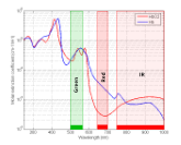
The differences in absorption between oxygenated (red) and deoxygenated (blue) blood can be used with paired red-IR LEDs to determine blood oxygenation percentage. See the MAX30100 sensor for an example.
During a pulse there is a wave of increase blood pressure through the arteries, slightly stretching the elastic arterial walls and bringing a pulse of highly oxygenated blood. This change in arterial size and increase concentration of blood is what is exploited to detect the pulse with PPG.
Green light is absorbed by red blood cells, but scattered by the tissues. Between pulses, scattered light will be reflected back out towards the incident light and can be detected. However, during a pulse, the small increase in blood volume leads to an increased absorption of the green light. This results in a reduction of reflected signal. We cab detect this increased absorbance by the reduction in reflection of green light.
Red/infra-red light is reflected by red blood cells. Between pulses most light is transmitted and scattered into the tissues. During a pulse the small increase in blood volume leads to an increased reflection of light by red blood cells, and a reduction in transmission. We can detect this increased scattering of light either by the reduction in IR transmission, or alternatively an increase in reflection.

Below we look at the main types and how to interface with them from different microcontrollers. You can also use one of these sensors to build a working heart monitor.
Analogue Sensors (KY-039/Pulsesensor.com)
Sensor types
IR-phototransistor sensors (KY-039) like the Keyes KY-039 use a bright infrared (IR) LED and a photo transistor to detect the reduced IR transmission or increased IR reflection during the pulse. These sensors are more suited to transmission use because of their construction.
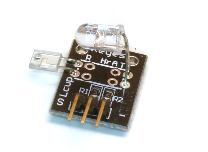
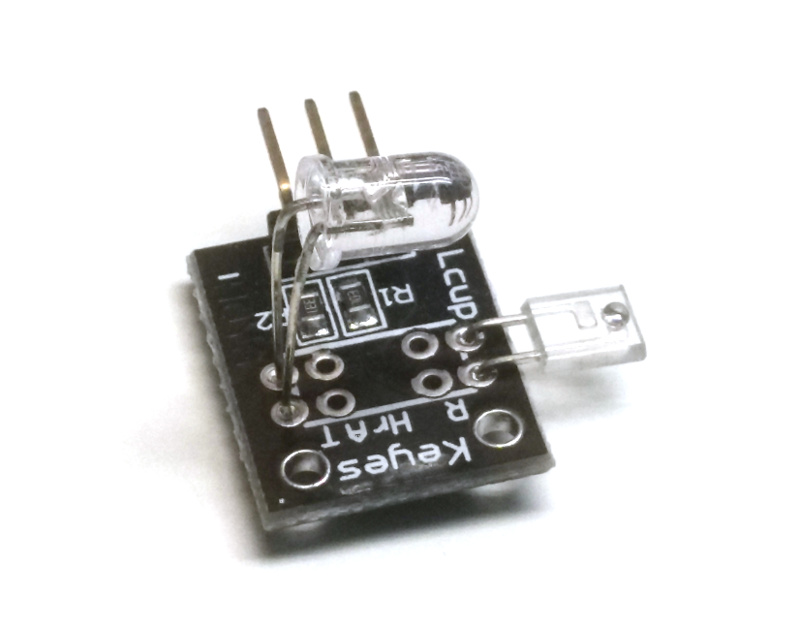
Green-light phototransistors like the PulseSensor.com function in reverse usign reflected, rather than transmitted light to detect the pulse. This is done using a rather pleasant green LED, which when wired up looks a bit like a tripod from the War of the Worlds. By using green light these sensors detect the reduction in reflection due to blood absorbing the green light. The circuitry for these sensors is a little more sophisticated than a rawlight sensor, with automatic amplification and noise cancellation features. This makes the subsequent HR calculation a little simpler. The sensors are similar to those found in wearable heart rate/fitness devices.
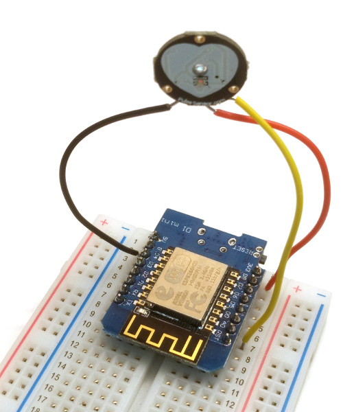
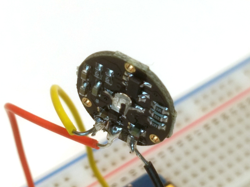
See this tutorial for an example of building a heart rate monitor using a Pulsesensor.com sensor.
Reading analogue sensors
The principal for reading both types of sensor is the same. With the sensor + connected to Vref (3.3V or 5V; depending on controller), and GND to GND, the measured value is readable via the S pin. The analogue output from this pin varies between GND (light completely blocked) and Vref (light completely passing).
The variation caused by the pulse is a tiny fraction of that caused by putting your finger in front of the sensor, so calculating the pulse value requires a bit of code (see later).
Raspberry Pi
Wire the + on the sensor to +3.3v on your Pi. While the sensor can handle 5V itself, the input voltage sets the max output from the S pin. More than 3.3V will damage your Pi's GPIO.
As the readings are analogue you will need a Analogue to Digital Converter (ADC) such as the MCP3008 between the sensor and your Pi. The Pi then communicates with the chip via SPI.
Add the MCP3008 to a breadboard, with the notch facing up towards your breakout board. Using hardware SPI we can wire the MCP3008 up as follows:
| MCP3008 | Raspberry Pi |
|---|---|
VDD (16) |
3.3V |
VREF (15) |
3.3V |
AGND (14) |
GND |
DGND (13) |
GND |
CLK (12) |
SCLK (11) |
DOUT (11) |
MISO (9) |
DIN (10) |
MOSI (10) |
CS/SHDN (9) |
CE0 (8) |
The analogue and digital ground pins are wired together here. This is fine since we aren't looking for highly accurate readings.
Wire the 3.3V and GND pins up first, leaving the SCLK, MISO, MOSI and CEO pins to wire to your Pi. They connect to pins 11, 9, 10 and 8 respectively, with the first 3 in order up one side of the GPIO, and the last on the other side, level with the first pin you connected.
Once connected you can use the gpiozero.MCP3008() interface to read values out directly.
import gpiozero
hr = gpiozero.MCP3008(channel=0)  # Set the channel if you're using a different one

>>> hr.value
    0.7663
To check that the sensor is responding correctly, try writing the values out in a loop (using end="\r"
keeps our output on a single line).
while True:
    print("%4f" % hr.value, end="\r")
If you put your finger between the emitter and sensor while running this you should see the number increase, indicating increased resistance as the light has to travel through your finger. Somewhere buried in the noisy variation you see is your heart beating.
MicroPython (ESP8266 inc. Wemos D1)
If you're running on a ESP8266 device you have access to an ADC pin, labelled as A0 on the Wemos D1. Once your sensor is wired to this pin you can use following MicroPython code to read the value from the sensor:
import machine
adc = machine.ADC(0)

>>> adc.read()
550
The values output by this ADC are integers in the range 0-1023. A reading of 550 is equivalent to 0.54 on a 0-1 scale.
Below is a plot of data from the Pulsesensor.com sensor, as read using a Wemos D1. Notice that the Pulsesensor.com sensor auto-calibrates the reading range.


BBC micro:bit
The micro:bit can read analog values on pins 0, 1, 2, 3, 4 and 10.
from microbit import *
>>> pin0.read_analog()
550
The values output by this ADC are integers in the range 0-1023. A reading of 550 is equivalent to 0.54 on a 0-1 scale.
To support developers in [[ countryRegion ]] I give a [[ localizedDiscount[couponCode] ]]% discount on all books and courses.
[[ activeDiscount.description ]] I'm giving a [[ activeDiscount.discount ]]% discount on all books and courses.
Digital sensors (MAX30100/RCWL-0530)
Digital sensors based on MAX30100 chips offer both heart rate sending and oximetry (oxygen saturation measurements). These include 2 LEDs (IR and visible red light) to detect pulse and oxygen saturation levels respectively.
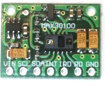
Oximeters pair two light emitters and receivers working at slightly different wavelengths. Using the different light absorbance profiles of oxygenated and deoxygenated blood it is possible to determine the level of O2 in the blood in addition to the pulse.

Reading digital sensors
The MAX30100 chip datasheet provides an I2C interface to read the resulting data, which can be interfaced directly to any I2C supporting micro controller. It is available at I2C channel 0x57 (87).
There was no simple interface available for connecting with a MAX30100 based sensor from a Raspberry Pi (the Intel IoT UMP project looks promising, but doesn't build on Pi as of September 2017). As a stop-gap I re-implemented a C library in Python. The source code is available. This currently works with Raspberry Pi only, although adapting to MicroPython should be as simple as writing an adaptor for the I2C API.
You can create an interface to your device/chip by creating an instance of the MAX30100 class.
import max30100
mx30 = max30100.MAX30100()
To read the sensor use .read_sensor(). This stores the current measurement, making this value available
under two properties. Historic values are in a queue.
mx30.read_sensor()

# The latest value is now available by .ir
mx30.ir
You can switch on O2 sensing as follows.
ms30.enable_spo2()
Subsequent calls to .read_sensor() will now populate the .red attribute.
# The latest value is now available by .ir and .red
mx30.ir, mx30.red
For more information on using the max30100 package, including the O2 saturation sensor, see the documentation on Github.
Calculating a heart rate
Regardless of what sensor you use, you will end up with the same output — a stream of values, indicating transmission or reflection of a particular wavelength of light.

There are a number of ways to calculate the heart rate from this data, but peak-counting is a simple and effective method. For a working example of how to do this see this Wemos D1 heart rate monitor.

