| Requirements | |||
|---|---|---|---|
| Pocket Etch-A-Sketch Not the really really tiny one. | amazon | ||
| 3D PrinterI have & recommend the Anycubic i3 Mega. | amazon | ||
| PLARed, white & black | amazon | ||
| 2x 5V 28BYJ-485V stepper motor. | amazon | ||
| 2x ULN2003A IC Darlington array, as stepper driver chip. | amazon | ||
| 1x 330Ω resistor for LED driven off Pi at 3V. | amazon | ||
| 2x 100μF-220μF capacitor To smooth motor/Pi power. | amazon | ||
| Protoboard Only need a bit. | amazon | ||
| Red, Yellow, Green LEDs Adjust resistor Ω to match. | amazon | ||
| 4xAA battery pack If it has a switch that's a bonus. | amazon | ||
| 3x18650 battery pack Or 4x, will be through regulator. | amazon | ||
| 2x 5-pin JST connectors To fit those on the stepper. | |||
| 3x 2-pin JST connectors I used a smaller one for the shutter. | |||
| 1x momentary switch For shutter. | |||
| 1x mercury/tilt switch For screen-clear check. | |||
| 2x screws To mount the circuit on the Etch-A-Sketch. | |||
| 2x bolts and washers To mount the motors to the frame. | |||
| Wire Plus some loose bits for tracks on the back. | |||
| Glue Hot glue to mount batteries, superglue to mount shutter, (optional) soft glue for camera mount. | |||
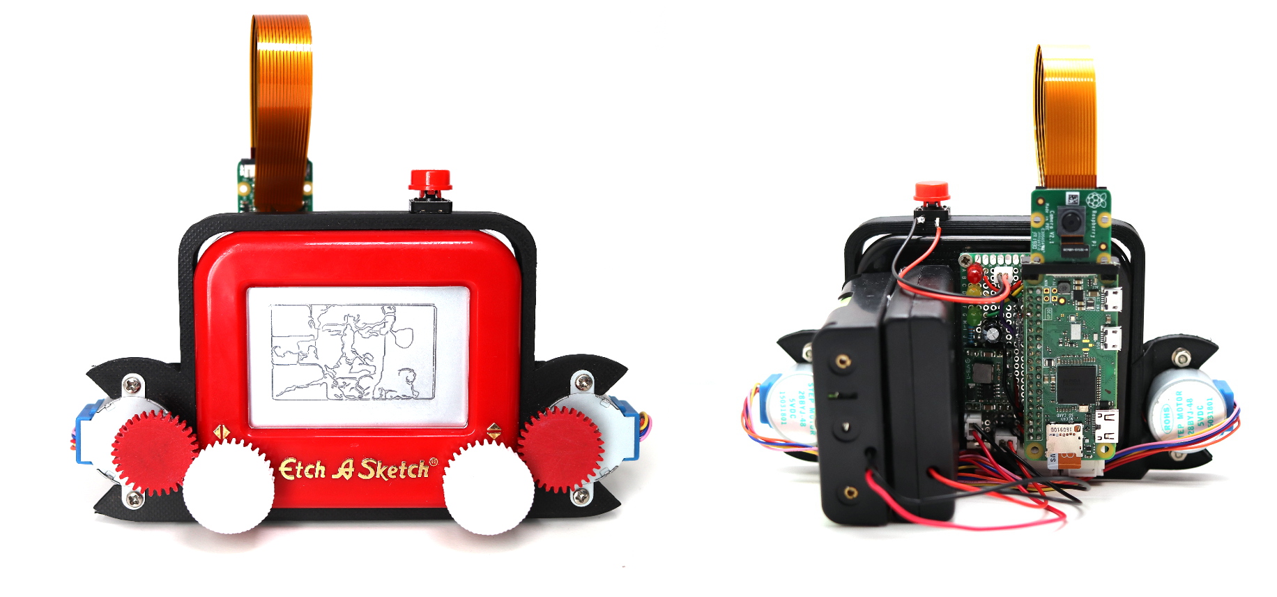
Etch-A-Sketch is built from a pocket Etch-A-Sketch and 6 individual 3D printed components. The control is handled by a Raspberry Pi Zero (or Zero W) and a custom circuit board containing motor drivers and inputs. The wheels are driven by two stepper type motors mounted on the 3D printed frame, through two 3D printed gears. The camera is mounted in the final 3D printed piece. The total build & print time should be around 1 day allowing for snacks.
3D Parts
There are 6 parts to the build. The first, the largest, is a frame which surrounds the Etch-A-Sketch and holds the stepper motors in place. There are two wheel gears (printed in white, orange in the image below) to replace the control wheels of the Etch-A-Sketch, and two driver gears (printed in red) for the steppers. Finally, there is a small camera mount which sits on the top of a Raspberry Pi Zero to hold the camera.
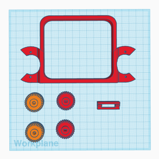
The parts are all available to download as a zip of STL files or to tinker with directly on TinkerCAD. The colours are optional, but allow the parts to match the aesthetic of the original Etch-A-Sketch.
Development
The Etch-A-Sketch comes with two white plastic control wheels for drawing with. On the original and the pocket Etch-A-Sketch these are mounted onto metal drive rods, and can be removed with a little force. The best approach is to get something long and thing (like a metal ruler) underneath and lever it up. Put cardboard under it to avoid damaging the case.
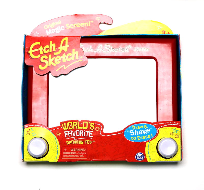
Once removed the original wheels (L) are replaced with the 3D printed look-a-likes (R) with a cog built into the lower half. The replacement wheels are slightly larger in diammeter and lower profile, but don't look out of place.
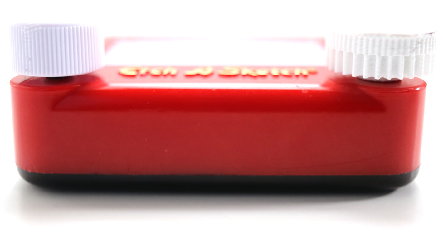
The Etch-A-Sketch is still completely usable with these wheels attached.
The modern full-size Etch-A-Sketch (sold as "classic") now has plastic drive shafts and the wheels are glued onto it. The only option here is to cut into them. Cutting into something that rotates is asking for an accident, so be careful.
The circuit
The power management, motor driver circuit, status lights and inputs were laid out on a perfboard. The Raspberry Pi is mounted in the centre of the board, with the motor driver on the right hand side and the rest of the circuit on the left.
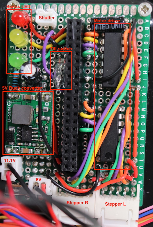
Most of the connections are under the board, using solder bridges and bits of wire. There are probably better ways to lay this out, particularly around the power-input where it got messy due to a busted component. The circuit diagram is given below.

The Fritzing file is available.
I had initially intended to have a flash mounted on the board too, but there wasn't enough room & in the end decided to omit it. An obvious improvement would be to have the status LEDs visible from the back (screen-side) of the camera, so you can see when it's grabbed a shot — although it currently works great for selfies.
The circuit board was mounted to the back of the Etch-A-Sketch with two small screws in the top of the board. I wasn't sure if this was going to break it, but it didn't.
To support developers in [[ countryRegion ]] I give a [[ localizedDiscount[couponCode] ]]% discount on all books and courses.
[[ activeDiscount.description ]] I'm giving a [[ activeDiscount.discount ]]% discount on all books and courses.
Power supply
The Etch-A-Sketch takes 4x AA batteries and 3x 18650 LiPo cells. The former is used for driving the motors (6V) while the latter (11.1V) powers the Raspberry Pi through a buck converter regulated at 5V. A 100μF capacitor is added to smooth the output.
The soldering in this bit of the board is an absolute mess as the first buck converter mounted was faulty and the second blew it's capacitor during testing. The secondary capacitor (added to smooth the output) saves the day.
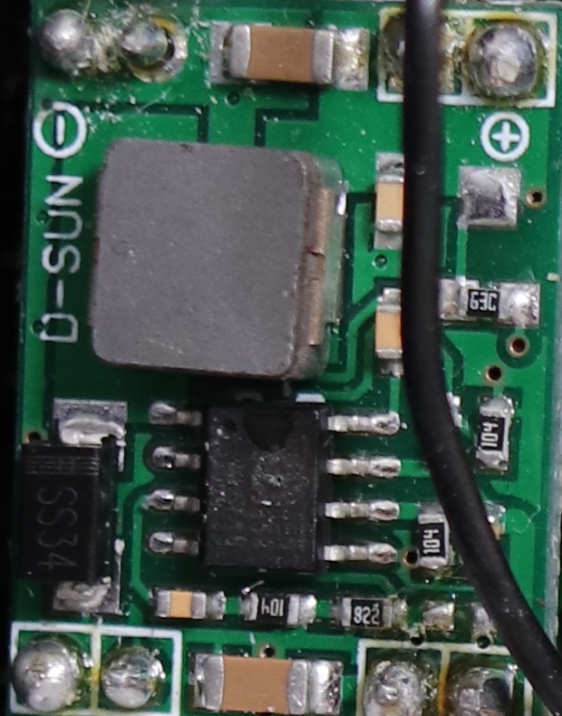
The Pi is doing some heavy processing during the graph generation (see later). The original plan was to power the Pi through the same AA batteries, but the power drop caused by the steppers ruled this out. Using a separate 4xAA pack solved this, but could only sustain the system for an hour or so.
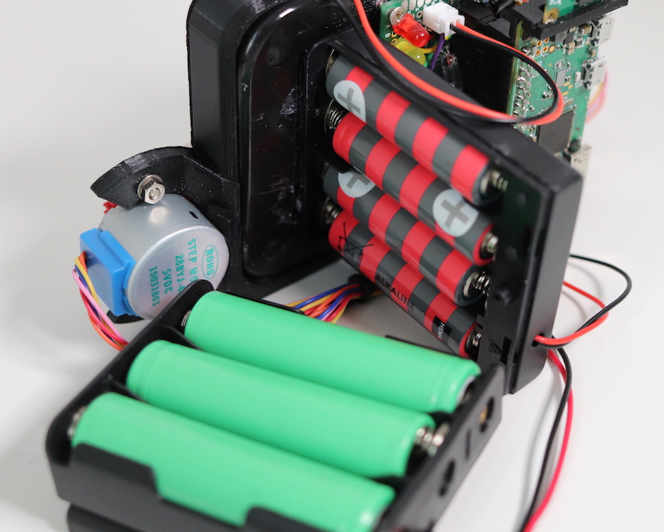
The LiPo cells are more than enough to keep the Pi ticking over for quite some time, until the voltage drops to ~2.2V (6.6V total, which through the regular is <5V). The AA cells are run down fairly quickly (10-15 pictures worth). When this happens it just stops drawing, no harm done.
The 4xAA battery pack is hot-glued onto the back of the Etch-A-Sketch. I scored a bunch of lines into the back to improve attachment (increase the surface area). The LiPo battery pack is in turn hot-glued onto the case for the AA battery, so can be removed by sliding it off.
The AA battery pack has an integrated power switch, while the LiPo cells use a switch on the main circuit board.
The frame
It took ~20 iterations to get to the final version, both of the frame (positioning, and for different steppers) and the gearing (to get enough torque).
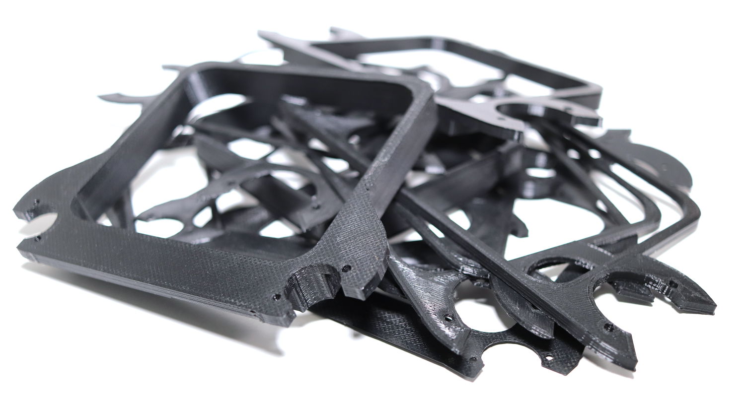
One useful tip is to print the frame prototypes at only 2mm thick, and use these to test the positioning and orientation. This allowed to rapid iteration through a lot of bad ideas. Unfortunately this doesn't work nearly as well for the gears, so I now have a box of 50 odd gear rejects.
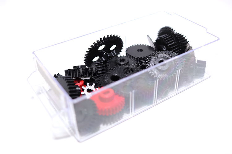
This would have been a lot simpler if the entire construction was 3D printed as the measurements would have been known from the start.
The frame slips over the Etch-A-Sketch from the front. The back part (black) of the Etch-A-Sketch actually sticks out a little and catches it. This was entirely accidental. You can glue the frame on, but I left it free in case something went horrifically wrong and I had to start over.
The two motors sit in the semi-circle mounts on the corner of the frame and can be secured with bolts, washers and nuts through the holes. I used a couple of random-sized ones I had lying around.

The motors are connected to the two JST sockets on the bottom of the board, with the connection going to the closest side (i.e. left-to-left). There was quite a bit of spare wire on my motors so it was bundled up with a wire-tie.
Motors & Drivers
To accurately plot an image we need precise movement. Stepper motors allow precise step-wise control rotation in either direction. In the final build of the Etch-A-Sketch I used two 5V 28BYJ-48 motors, driven using ULN2003 ICs.
The motors are powered from 4xAA batteries (6V) a little over a full charge, but nothing to be concerned about. This combination of driver and motor provided enough torque to turn the Etch-A-Sketch wheels at 1:1 ratio and still give reliable movement.

The stepper motors drive the Etch-A-Sketch through 3D printed PLA cogs. These are the same size and ratio as the white plotter wheels mounted earlier. This allows us to drive the wheels without using an external hacks (belts, cables, etc.)

What didn’t work
Finding a combination of driver and stepper motor which could drive an Etch-A-Sketch from 4xAA batteries reliably took a large chunk of the build time.
The initial prototype used a smaller stepper motor than the final design, to try and keep things as portable as possible. Turning the Etch-A-Sketch wheels by hand is not difficult, but the little stepper couldn’t do it. Stepper motor driver boards (which can overdrive voltage with regulated current to get maximal torque) did better but it was still not enough.
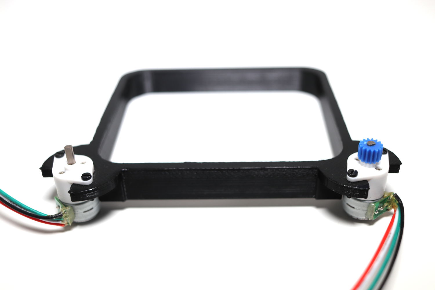
Switching to the larger stepper offered more torque, but now the power was limited by the 6V battery pack — it was not really over-driving at all. The ULN2003 finally solved the problem by allowing the energising of paired adjacent coils — effectively doubling the torque. This gave enough leeway to continue turning even if the input voltage from the AA batteries drops.
Inputs & Outputs
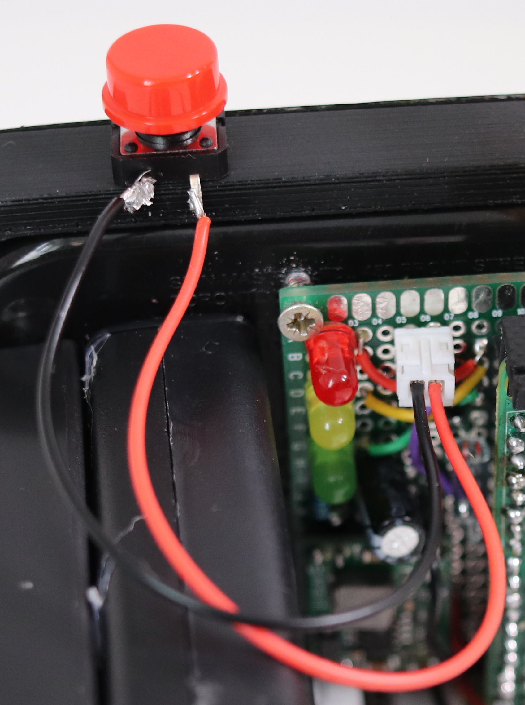
Taking a picture is triggered by the shutter button, wired up as a standard gpiozero.Button using .wait_for_press() to detect the click. The switch is a standard momentary switch, with two legs pulled off (so they don't show on the front) and then superglued to the frame.
The same approach is used for the tilt sensor — a mercury-type switch — which is orientated to be triggered when the Etch-A-Sketch is face-down. There is no way to detect whether the screen is clear, so we have to assume the user has some common sense.
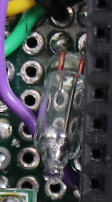
You could detect a certain number of on/off states from the tilt switch to detect shaking, or add a separate shake sensor.
Packaging Python Applications with PyInstaller by Martin Fitzpatrick — This step-by-step guide walks you through packaging your own Python applications from simple examples to complete installers and signed executables.
Status LEDs
There are 3 status LEDs on the back of the Etch-A-Sketch to give some feedback on what is currently happening. These are powered directly from the GPIO. As only a single LED is lit at any point only a single current-limiting resistor is needed.
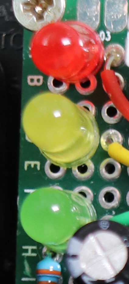
The possible states are shown below along with what is required to move past this status (in the code) —
- stopped — red on; waiting to be tipped over to clear the screen (until tilt switch)
- ready — green on; waiting to take a picture (until shutter press)
- processing — yellow on; we have an image and it’s being processed
- drawing — yellow pulsing; we are drawing the image
Once the drawing completes the status resets back to stopped with the red light on. At this point you can tip the Etch-A-Sketch over to clear the screen and start again.
The camera
The Etch-A-Sketch camera itself is just a standard Raspberry Pi camera module with a Pi Zero cable interfaced using picamera. To hold the camera in place there is a 3D printed mount which clips loosely to the top of the Pi Zero. The camera can sit in the small notch on top.
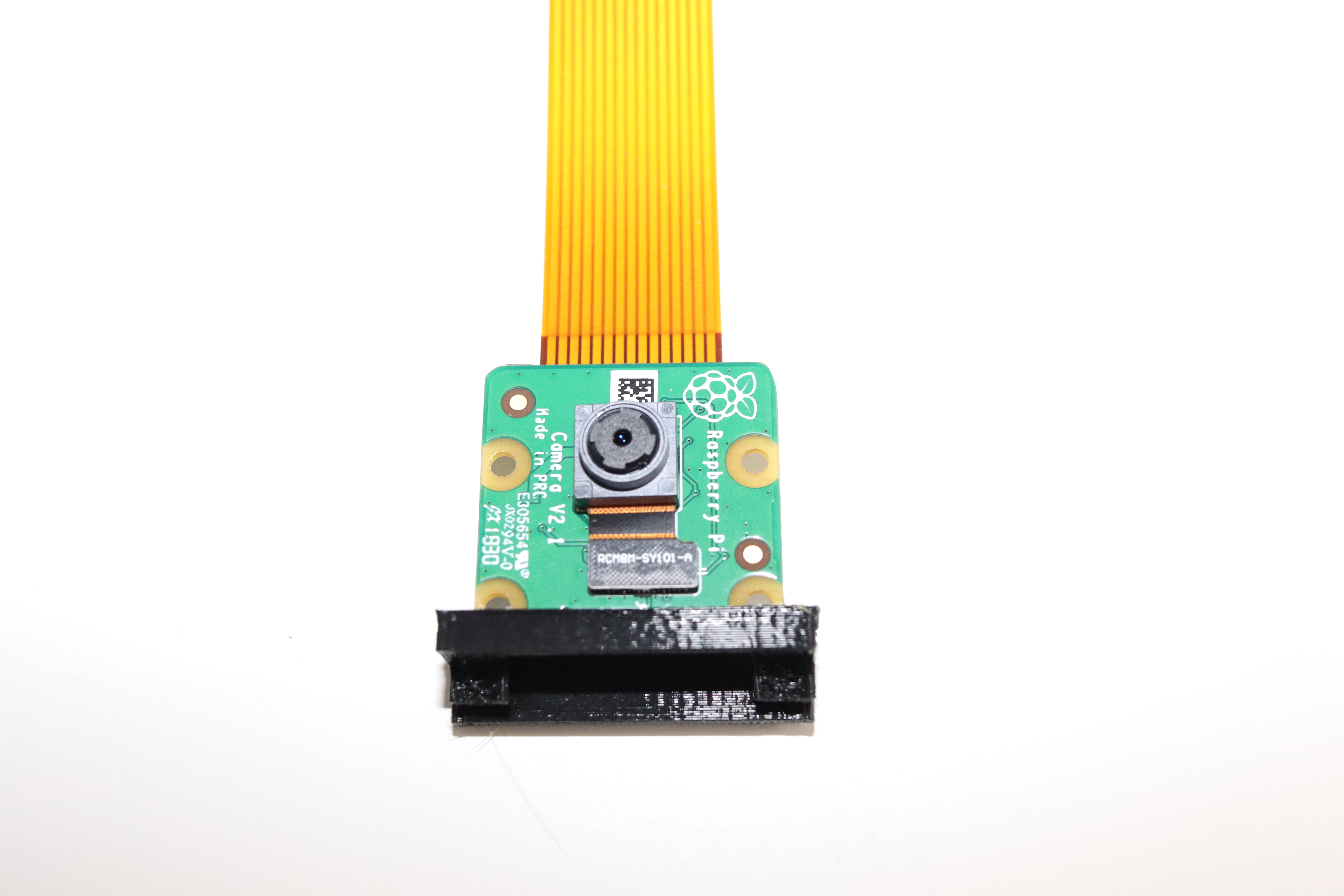
The fixture isn't particularly tight, but some soft glue is enough to keep the camera secure when shaking (and is easily removable).
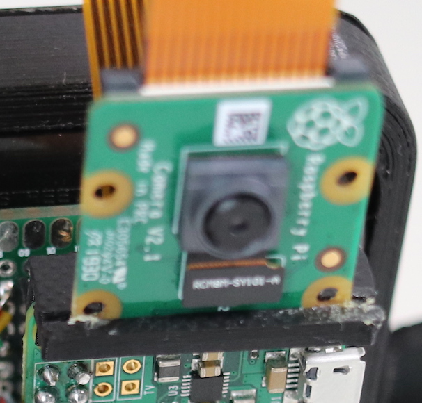
It should be possible to adjust the 3D printed part to make this a tighter fit.
The code & command-line tools
The camera code main.py is shown below, containing the main execution flow for the camera, the status LED control and inputs from the shutter and tilt switch. The camera starts up in Complete state with the red LED illuminated and must be turned over and shaken before taking the first shot (it assumes there may already be a photo present).
import time
from gpiozero import Button, LED, PWMLED
import graph, plotter, camera

red = LED(21)
yellow = PWMLED(20)
green = LED(16)

shutter = Button(25)
tilt = Button(12)

# Status light shortcuts.
def status_ready():
    red.off()
    yellow.off()
    green.on()

def status_complete():
    green.off()
    yellow.off()
    red.on()

def status_processing():
    green.off()
    red.off()
    yellow.on()

def status_drawing():
    green.off()
    red.off()
    yellow.pulse()

def main():
    while True:

        status_complete()

        # Wait for flip & shake.
        tilt.wait_for_press()
        time.sleep(1)

        # Setup the camera interface.
        camera.prepare()
        status_ready()

        # Wait for shutter, then take picture.
        shutter.wait_for_press()
        status_processing()
        image = camera.take_photo()
        image = camera.process_image(image)

        # Process the image & generate plotter moves.
        moves = graph.generate_moves(image)

        # Draw the paths.
        status_drawing()
        plotter.enqueue(moves)

        # Complete.

if __name__ == "__main__":
    main()
The camera is started up using cron at reboot using the following line.
@reboot python3 /home/pi/etchasnap/main.py
Once started the camera will continue to run in an infinite loop, waiting for the screen to clear, waiting for the shutter, taking a picture, drawing it, waiting for the screen to clear, and so on. To turn the camera off the power to the Raspberry Pi (and optionally the steppers) can be cut.
What's next
Now we have an assembled Etch-A-Snap and the outline control code, we can move on to the code to take and process the photos to get ready to draw.
Create GUI Applications with Python & Qt6 by Martin Fitzpatrick — (PyQt6 Edition) The hands-on guide to making apps with Python — Over 10,000 copies sold!
Continue reading the Etch-a-Snap series with Image Processing, Etch-A-Snap

